Computer Architecture
The specifications around which a computer’s organizational layout is defined.
- Microcontroller: Embedded all in one device. Specific tasks
- Microprocessor: Processor ←> memory / timer. More generic.
| RISC | CISC |
|---|---|
| simpler | complex |
| fixed len: ‘32’ only | variable len: 32, 64 bit |
| multiple reg set | single reg set |
| single cycle | multi cycle |
| hardware control | microprogram control |
| highly pipelined | less pipelining |
only LOAD STORE | many memory instructions |
ARM
Advanced RISC Machine. It’s a family of instruction set architectures (ISAs) for computer processors. ARM processors are used in a variety of devices, including mobile phones, portable media players, and GPS navigation systems.
Features of ARM
- Conditional Instructions
- Load / Save Architecture
- 32 bit width
- A general shift/ALU op in a single clock-cycle
- 3 addr instruction format
Tradeoffs
- Moving data from one place to another: A common misconception is most time goes in (ALU work)
- Used to calc address/data of where the program is stored (1).
- The RISC compiler bridges the gaps, We should also design a good ISA
| Data movement | 43% |
|---|---|
| Control Flow (branching) | 23% |
| ALU | 15% |
| Comparison | 13% |
| Logical | 5% |
Instead, we can start a new fetch phase after the first decode is in progress: 3-Stage Pipeline
| Fetch | Decode | Execute |
|---|---|---|
| one → | by→ | one→ |
- Concurrency: via Pipelining
- Caching: To reduce average time for frequently used data
- Super Scaling → HPCA
ARM Instructions
- Shortform:
ADD,SUBCondition (modifier):EQ,EG,MI,GT,LE - {S} optional suffix: Sets
N,O,C,V,Z - {Rd}: Reg Destination
- Operand 1 and 2
- Either register or immediate value
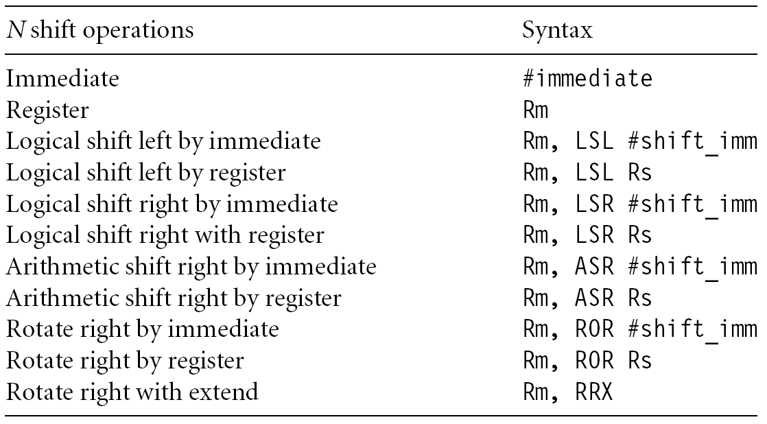
- Flexible: Can be immediate value or a register with optional shift
They can be classified as:
- Data Proc:
MOV, ADD, SUB - Data Transfer:
LDR, STR - Control Flow:
B, BL, BEQ, BGT
Program Structure
Addr | Instr, Data
------------------
set	 | .text
by 	 | ADD <instr>
proc    |
	 | .data
	 | var <x>
	 | .end
7 ARM modes
| code | mode |
|---|---|
| 10000 | user |
| 10001 | FIQ |
| 10010 | IRQ |
| 10011 | SUPER |
| 10111 | ABORT |
| 11011 | Undef |
| 11111 | System |
Register Windows
- Large number of registers
- Processor entry / exit moved to visible windows to give each procedure access to new registers.
- Saves state on stack, and then branch
- This reduces traffic b/w processor ←> memory
Delayed Branches
They use delayed branches so it doesn’t interrupt the smooth flow as we know a branch can result in T/F. But it isn’t great for super-scalar processors.
Status Registers (SR)
The state of CSPR → SPSR on every transition
- N: prev was -ve
- Z: produces 0
- C: carry out
- V: prev was signed bit
Flags
I = 1, disables IRQ F = 1, disables FIQ T bit: (arch with thumb mode only) T= 0 (arm state) T = 1 (thumb state)
Thumb Mode: 16 bit
- Only the reg:
r0-7are used - narrow data bus improves perf from memory
- subset of functionality of the ARM instruction set
Memory System
- 8 bit signed/unsigned
- 16 bit signed/unsigned: aligned on 2 byte memory
- 1 word signed/unsigned. aligned on 4 byte memory
- A word in ARM is 32 bit
Important
- LOAD: memory value → reg
- STORE: reg → memory
Warning
STORE [R1][R2] This is not allowed
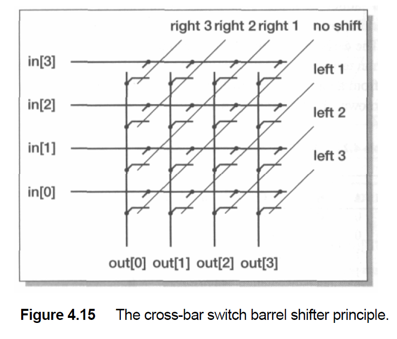
Barrel Shifter
The barrel shifter in ARM assembly can be used to perform efficient multiplication by powers of two, sums, and differences.
- Multiplying by:
MOV Ra, Ra, LSL #n - Multiplying by:
2n + 1→Ra = Ra + (Ra << n)
ADD Ra, Ra, Ra, LSL #n- Multiplying by
2n - 1→Ra = (Ra << n) - Ra
RSB Ra, Ra, Ra, LSL #nCross Bar Switch
Multiplying by 6
We can calculate 6 * Ra as:
- Multiply
Raby 2 usingMOV Ra, Ra, LSL #1. - Multiply
Raby 3 (which is2 * 1 + 1) usingADD Ra, Ra, Ra, LSL #1.
MOV Ra, Ra, LSL #1        ; Ra = Ra * 2
ADD Ra, Ra, Ra, LSL #1    ; Ra = Ra + Ra * 2 = Ra * 3
ADD Ra, Ra, Ra, LSL #1    ; Ra = Ra + Ra * 3 = Ra * 6
Multiplying by 45
We can calculate 45 * Ra as:
- Multiply
Raby 2 usingMOV Ra, Ra, LSL #1. - Multiply
Raby 22 (which is2 * 11) usingADD Ra, Ra, Ra, LSL #1. - Add
RatoRa * 22usingADD Ra, Ra, Ra, LSL #1. - Add
RatoRa * 44to getRa * 45.
MOV Ra, Ra, LSL #1 ; Ra = Ra * 2
ADD Ra, Ra, Ra, LSL #1 ; Ra = Ra + Ra * 2 = Ra * 3
ADD Ra, Ra, Ra, LSL #1 ; Ra = Ra + Ra * 3 = Ra * 6
ADD Ra, Ra, Ra, LSL #1 ; Ra = Ra + Ra * 6 = Ra * 12
ADD Ra, Ra, Ra, LSL #1 ; Ra = Ra + Ra * 12 = Ra * 24
ADD Ra, Ra, Ra, LSL #1 ; Ra = Ra + Ra * 24 = Ra * 48
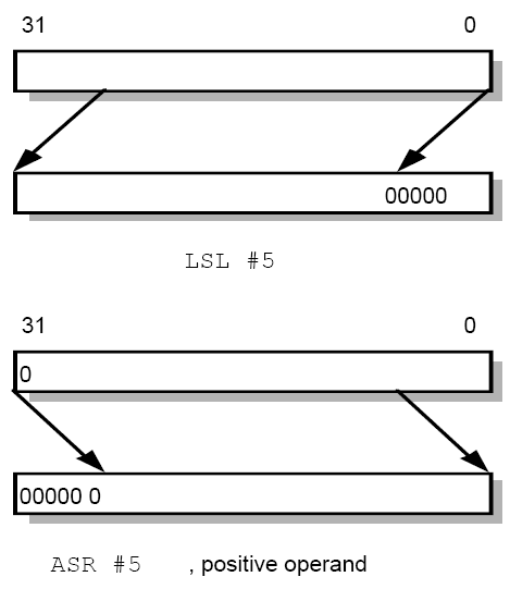
RSB Ra, Ra, Ra, LSL #1 ; Ra = Ra * 48 - Ra = Ra * 45LSL, LSR

MOV  R0, R2, LSL #2 @ R0:=R2<<2
                    @ R2 unchanged

Example: 0…0 0011 0000
Before R2=0x00000030
After  R0=0x000000C0
       R2=0x00000030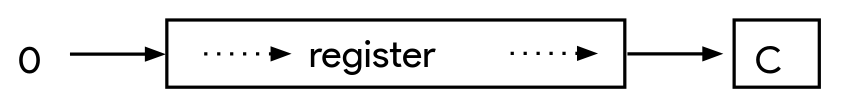
MOV  R0, R2, LSR #2 @ R0:=R2>>2
                    @ R2 unchanged

Example: 0…0 0011 0000
Before R2=0x00000030
After  R0=0x0000000C
       R2=0x00000030
ASR (preserves the MSB)
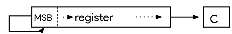
MOV  R0, R2, ASR #2 @ R0:=R2>>2
                    @ R2 unchanged

Example: 1010 0…0 0011 0000
Before R2=0xA0000030
After  R0=0xE800000C
       R2=0xA0000030
ROR, RRX
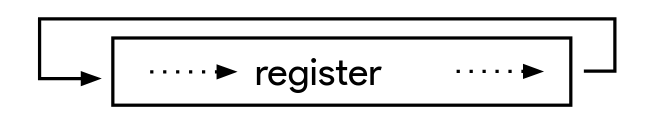
MOV  R0, R2, ROR #2 @ R0:=R2 rotate
                    @ R2 unchanged

Example: 0…0 0011 0001
Before R2=0x00000031
After  R0=0x4000000C
       R2=0x00000031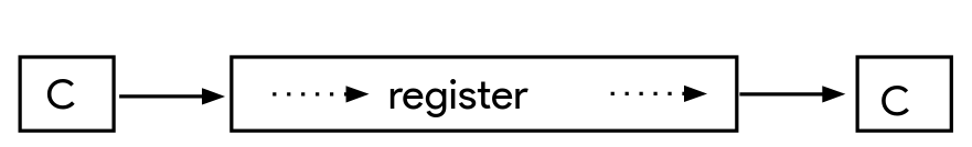
MOV  R0, R2, RRX    @ R0:=R2 rotate
                    @ R2 unchanged

Example: 0…0 0011 0001
Before R2=0x00000031, C=1
After  R0=0x80000018, C=1
       R2=0x00000031
Logical/Arithmetic
Shifted Register Operands
It is possible to use a register to specify the number of bits to be shifted; only the bottom 8 bits are significant.
@ array index calc
ADD R0, R1, R2, LSL R3 @ R0 := R1+R2*2^R3

@ fast mult R2 = 35 * R0
ADD R0, R0, R0, LSL #2 @R0` = 5xR0
RSB R2, R0, R0, LSL #3 @R2 = 7xR0`
Table
C to ASM
- A = B + C;
ADD R0, R1, R2 ; A = B + C - D = A – C; “RSB R3, R2, R0 ; D = A - C`
- F = (G + H) – (I + J) use the register
R0toR4as operands F to J respectively.
ADD R5, R1, R2   ; R5 = G + H
ADD R6, R3, R4   ; R6 = I + J
SUB R0, R5, R6   ; F = (G + H) - (I + J)
G = H + A [10].
LDR R3, [R2, #40] ; Load A[10] into R3 (40 bytes offset)
ADD R0, R1, R3 ; G = H + A[10]`
Branch Instructions & Addressing Modes
Syntax: B{<cond>} Label
BL{<cond>} Label
BX{<cond>} Rm
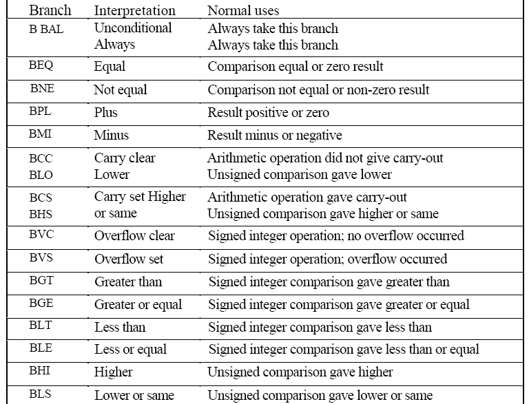
BLX{<cond>} RmFlow control instructions
| B | Branch | Program Counter = Label |
|---|---|---|
| BL | Branch & Link | 1: PC will be copied to R14 the Link Register (LR) before branch is taken.2: Program Counter = Label |
| BX | Branch Exchange | Used for changing ARM to Thumb mode or from Thumb mode to ARM mode. |
| BLX | Branch Exchange with link | ^^ |
Branch Instruction- (Unconditional)
B  label
...
label: ...
Conditional Branch Instruction
MOV  R0, #0
loop: ...
	ADD  R0, R0, #1
	CMP  R0, #10
	BNE  loop
Ex: Add 2 numbers A,B
LDR: Memory → Reg STR: Reg → Memory
.DATA; // declare all vars or memory locations
	A:  .WORD 0xABCDE
	B:  .WORD 0x11111
	C:  .WORD 0xC3413

.TEXT
LDR R1,=A
LDR R2,=B
LDR R3,=C

LDR R5, [R1]
LDR R6, [R2]
ADD R7, R5, R6
STR R7, [R3]
Ex: Sum of N numbers
.DATA; // declare all vars or memory locations
	A:  .WORD 10,20,30,40,50,60,70,80,90,100
  SUM:  .WORD 0

.TEXT
LDR R1,=A   ;
LDR R2,=SUM ;
MOV R4,#0   ; INITIALISATION (move by a word)
MOV R5,#1   ; COUNT register
L1: LDR R3, [R1]
ADD R4,R4,R3 ; Add next element in the array.
ADD R1, R1, #4 ; address to the next data
ADD R5, R5, #1 ; increment the count register
CMP R5, #11 ; Check whether all numbers are added
BNE L1 ; Else branch to L1 location
STR R4,[R2] ; store the result in location SUM.
SWI 0X011 ; logical end of the program.Table
LDR R1, =A    // Load address of A into R1
LDR R2, [R1]  // Load value at address A into R2
If A is a label in memory, R1 will hold the memory address of A, not the value stored at A.
Addressing Half Words
Program to find the sum of N numbers using half word
.DATA
  A:  .HWORD   0x10,0x20,0x30,0x40,0x50,0x60,0x70, 0x80,0x90, 0x0100
  SUM:  .WORD 00
.TEXT
	LDR R1,=A
	LDR R2,=SUM
	MOV R4,#0   ;INITIALISATION
	MOV R5,#1   ;COUNT
L1: LDRH R3,[R1]
ADD R4,R4,R3
ADD R1,R1,#2
ADD R5,R5,#1
CMP R5, #11
BNE L1
STRH R4, [R2]
SWI 0X011Byte Data
Program to find the sum of N numbers using Byte Data
; SUM OF N NUMBERS
; DATA GIVEN

.DATA
  A: .BYTE 1,2,3,4,5,6,7,8,9,10
SUM: .word 0
.TEXT
	LDR R1,=A
	LDR R2,=SUM
	MOV R4,#0   ;INITIALISATION
	MOV R5,#1   ;COUNT
L1: LDRB R3,[R1]
ADD R4,R4,R3
ADD R1,R1,#1
ADD R5,R5,#1
CMP R5, #11
BNE L1
STRB R4,[R2]
SWI 0X011Addressing memory locations
- Memory is addressed by a register and an offset. There are 3 ways to offset!
LDR R0, [R1] @ mem[R1]Immediate
LDR R0,[R1,#4] @ mem[R1+4]Register
LDR R0,[R1,R2] @ mem[R1+R2]Scaled Register
LDR R0,[R1,R2,LSL #2] @ mem[R1+4*R2]Addressing Modes
Preindexing or Preindexing without writeback
LDR Rd, [Rn, OFFSET]

LDR  R0, [R1, R2]  @ R0=mem[R1+R2]
                   @ R1 unchanged
.DATA
A: .WORD 10,20,30,40,50,60,70,80,90,100
SUM: .WORD 0
.TEXT
LDR R1,=A
LDR R2,=SUM
MOV R4,#0 ; INITIALISATION
MOV R5,#1 ; COUNT registerL1: LDR R3, [R1, #4]
ADD R4,R4,R3 ; Add next element in the array.
ADD R1,R1,#4 ; useless
ADD R5, R5, #1 ; increment the count register
CMP R5, #11 ; Check whether all numbers are added
BNE L1 ; Else branch to L1 location
STR R4,[R2] ; store the result in location SUM.
SWI 0X011 ; logical end of the program.Preindexing with Writeback or Autoindexing
LDR Rd, [Rn, OFFSET]!
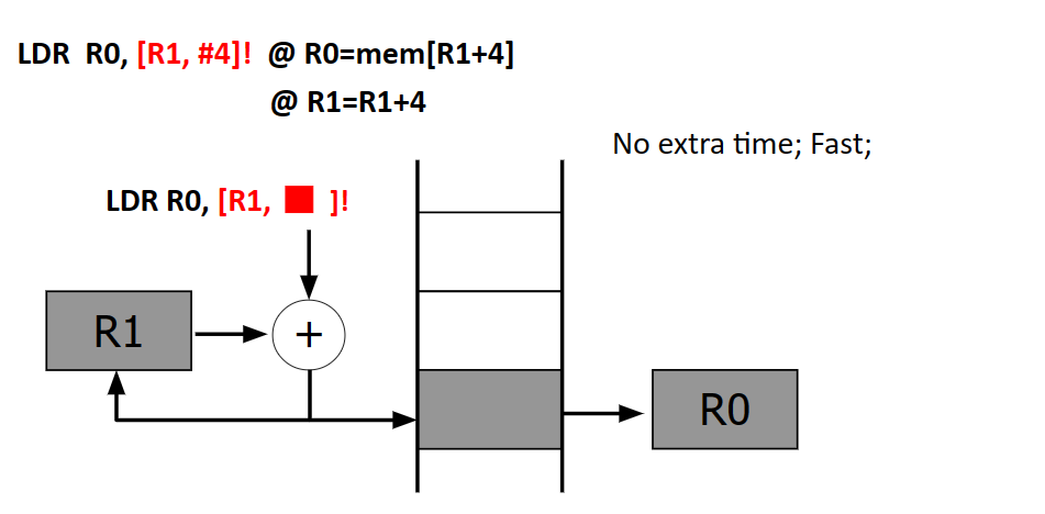
LDR  R0, [R1, R2]! @ R0=mem[R1+R2]
                   @ R1=R1+R2
.DATA
A: .WORD 10,20,30,40,50,60,70,80,90,100
SUM: .WORD 0
.TEXT
LDR R1,=A
LDR R2,=SUM
MOV R4,#0 ; INITIALISATION
MOV R5,#1 ; COUNT registerL1: LDR R3, [R1,#4]!
ADD R4,R4,R3 ; Add next element in the array.
ADD R5, R5, #1 ; increment the count register
CMP R5, #11 ; Check whether all numbers are added
BNE L1 ; Else branch to L1 location
STR R4,[R2] ; store the result in location SUM.
SWI 0X011 ; logical end of the program.Post indexing
LDR Rd, [Rn], OFFSET
LDR  R0, [R1], R2  @ R0=mem[R1]
                   @ R1=R1+R2
Load Multiple
!write back
Encoding
Block Transfer Instruction: LDM