Designing and Simulation of Network Topology using Cisco Packet Tracer
UE23CS252B: Lab_1
Name: Nathan Matthew Paul SRN: PES2UG23CS368 Section: 4F
Objectives
- To understand the purpose of Cisco Packet Tracer.
- To navigate, choose network and end devices and customize them.
- To interconnect devices and configure them using simple interface.
- To become familiar with building topologies in Packet Tracer.
- To simulate data interactions traveling through a network.
Prerequisites
This lab assumes some understanding of the building blocks of communication networks and internet. At this point, we haven’t discussed other protocols but you may use Packet Tracer in later labs to discuss those as well. Several types of devices and network connections can be used. For this experiment we will keep it simple by using end devices, switches, routers, and connections.
Steps to install Cisco Packet Tracer:
- Go to the download page: Visit this link: Download Cisco Packet Tracer
- Download Packet Tracer: Scroll down and download the version compatible with your operating system (Windows or Linux).
- Install Packet Tracer: Once the download is complete, run the installer and follow the on-screen instructions to complete the installation.
- Disable your internet connection: Before launching Packet Tracer for the first time, turn off your internet connection. This will prevent it from asking for registration.
- Launch Packet Tracer: Open the installed Cisco Packet Tracer. Since you are offline, it will allow you to use the program without requiring registration.
Task 2 (Mandatory)
In this task, students should explore how to add interfaces to the router.

Submission
Students are expected to take the screenshot of both the Topologies with the successful message after packet transmission.
You are to Provide:
- Screenshots of successful Transmission across all.
- All the addresses through a well defined routing table including hop table.
- The routing tables in all the routers in Topology -2.
Screenshots
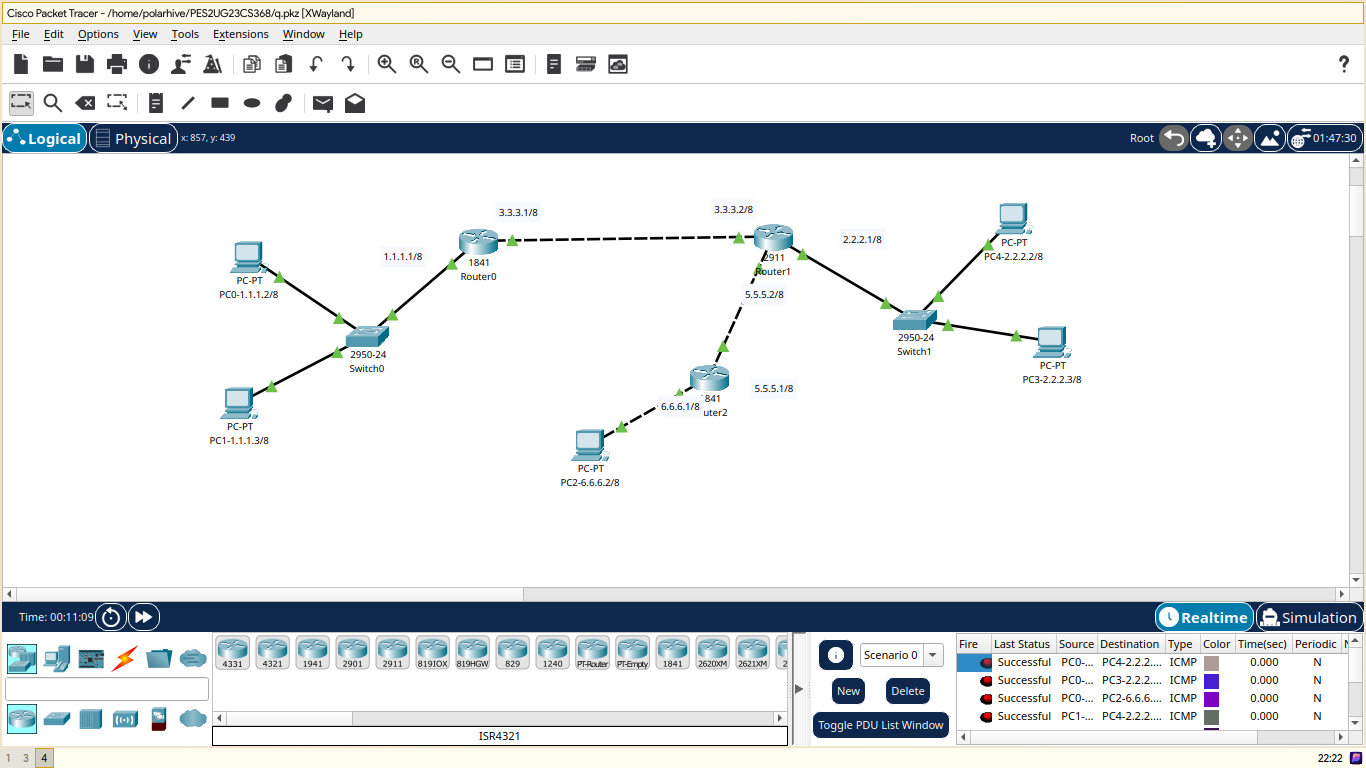
Topology
PC0

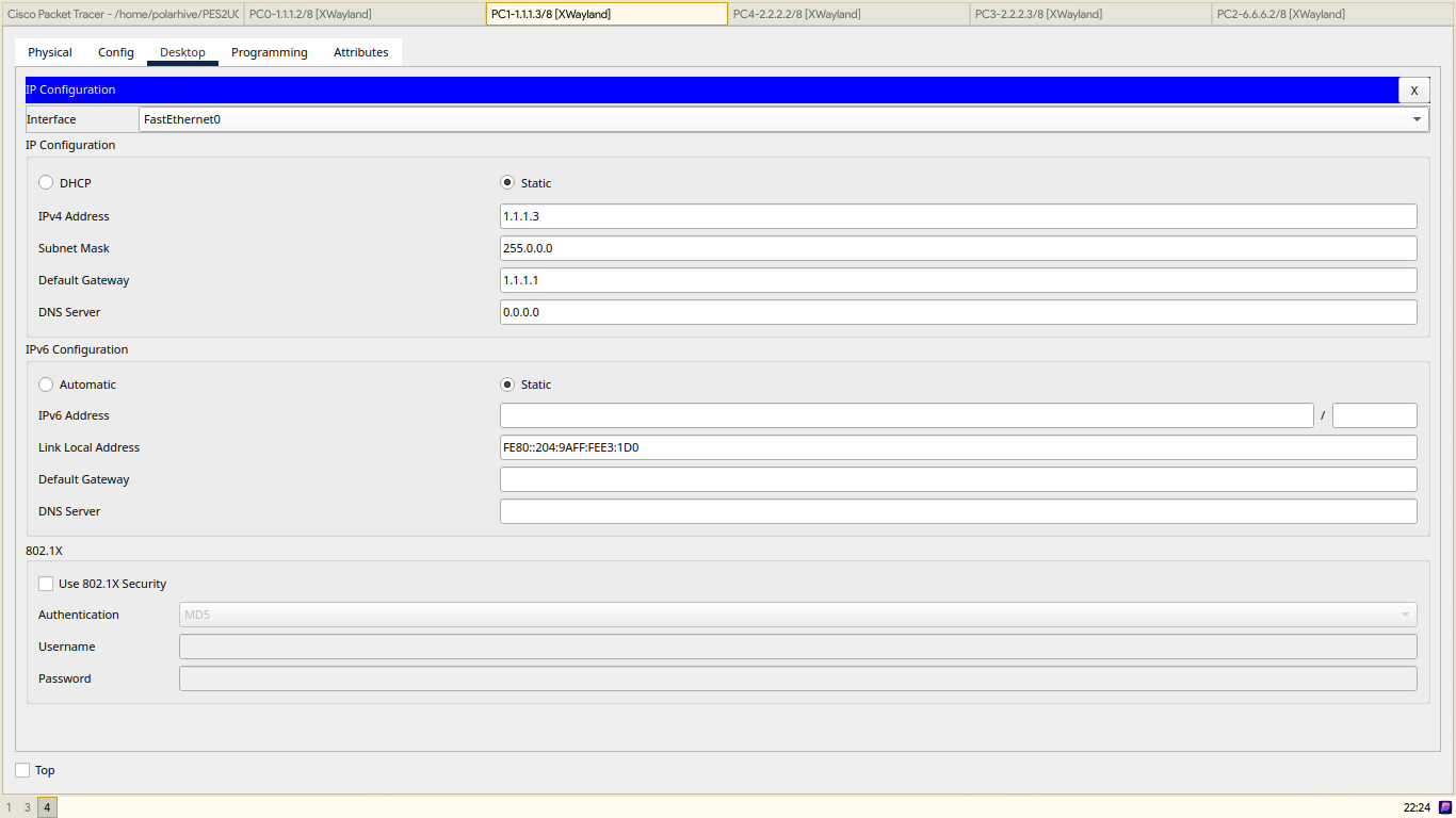
PC1
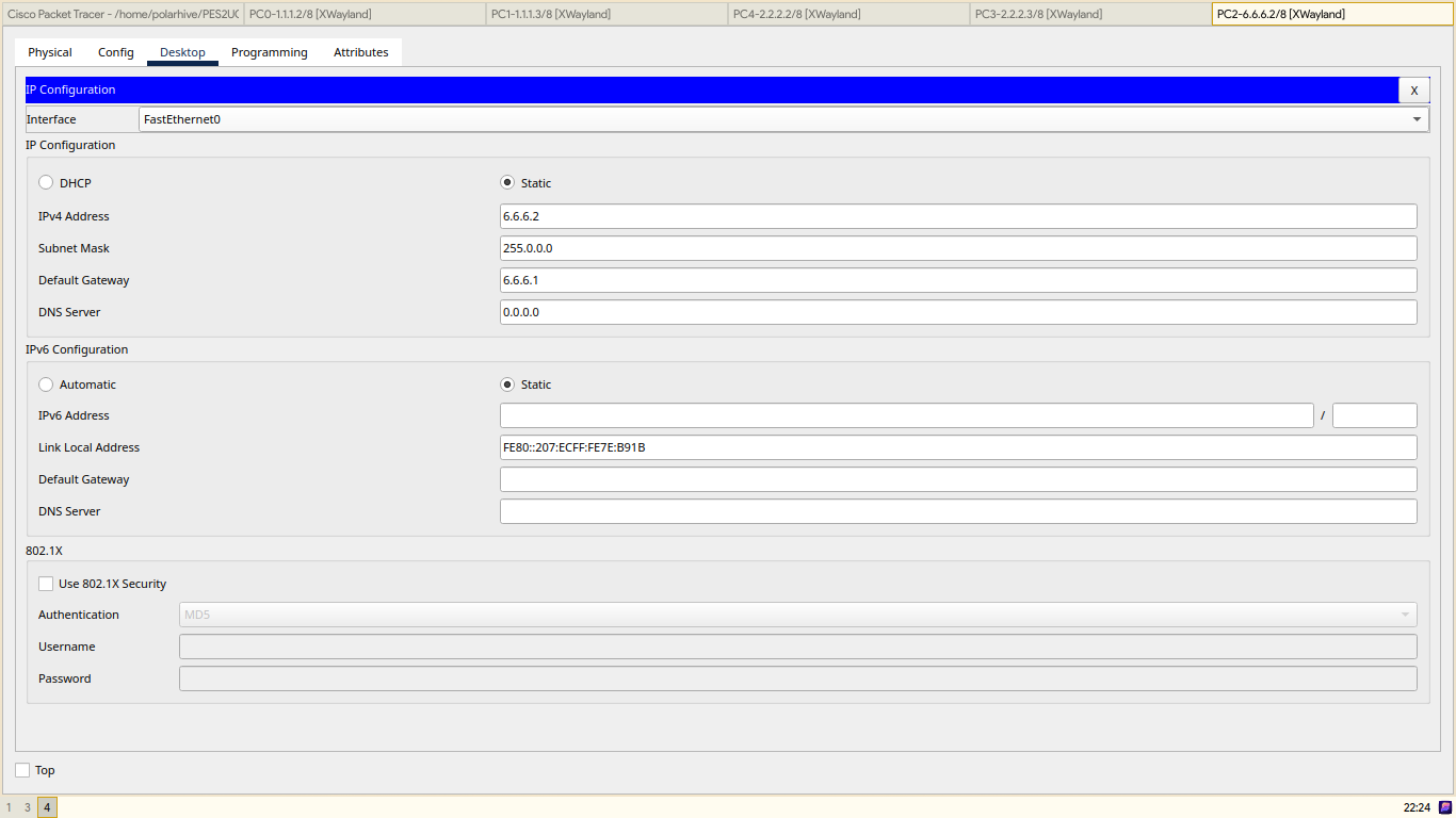
PC2
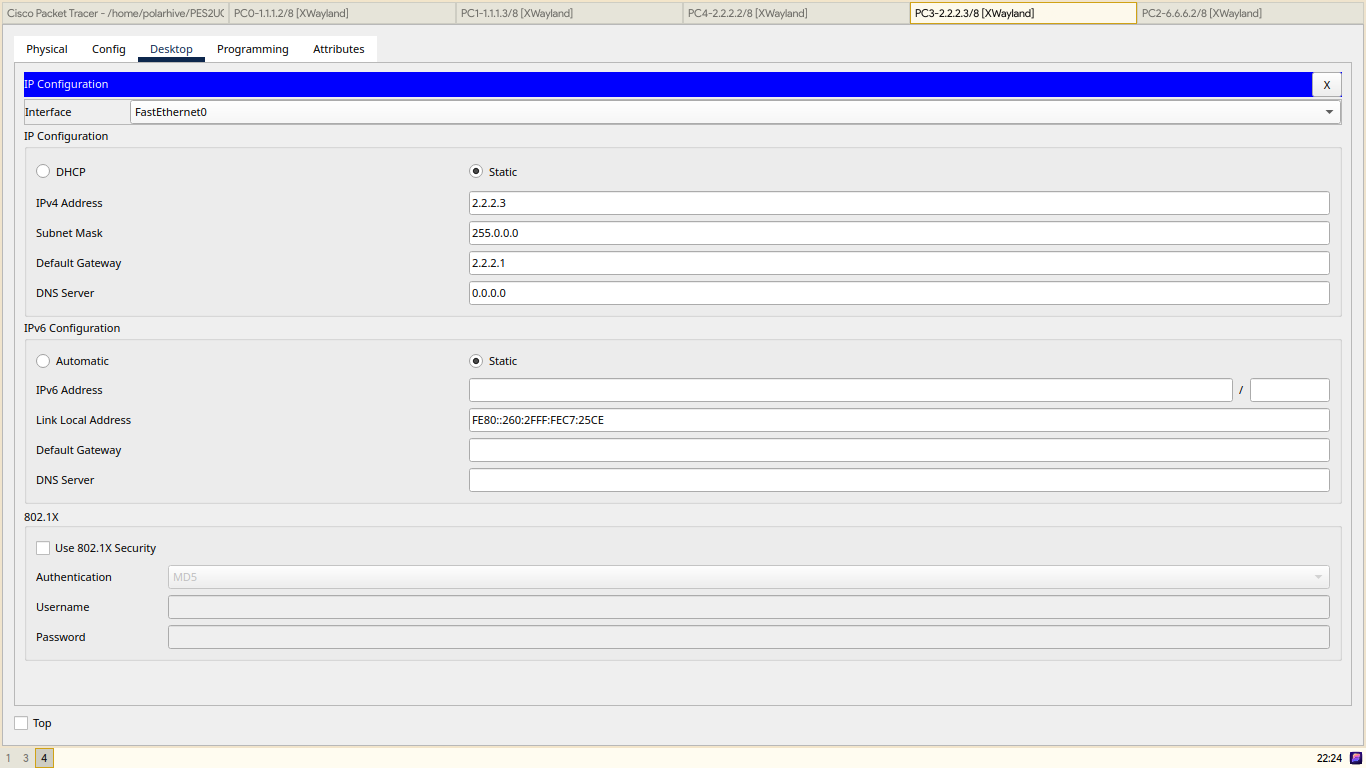
PC3
PC4
Router0


Router1

Router2

Routing Table
PC Config
| PC # | IP | Gateway |
|---|---|---|
| PC0 | 1.1.1.2 | 1.1.1.1 |
| PC1 | 1.1.1.3 | 1.1.1.1 |
| PC2 | 6.6.6.2 | 6.6.6.1 |
| PC3 | 2.2.2.3 | 2.2.2.1 |
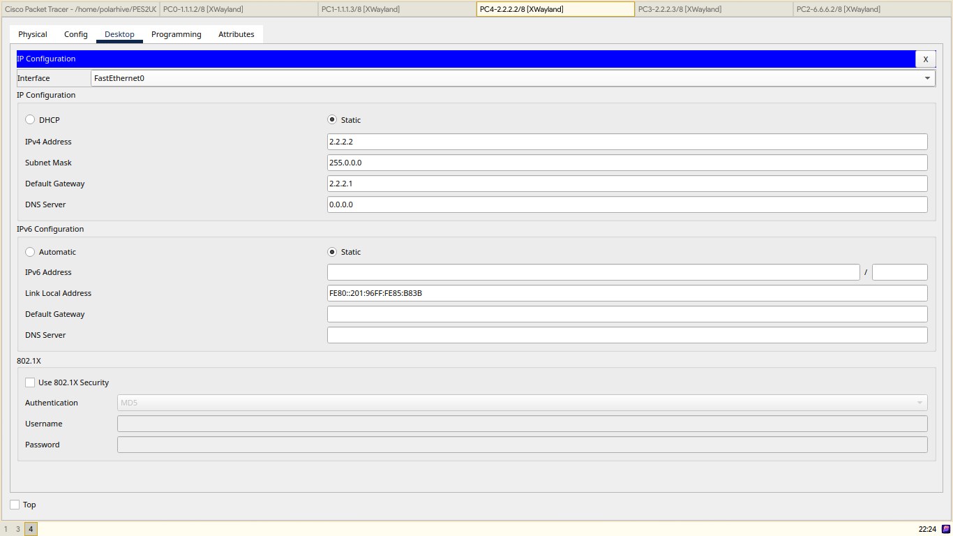
| PC4 | 2.2.2.2 | 2.2.2.1 |
Router Config
| Router # | Interface | IP |
|---|---|---|
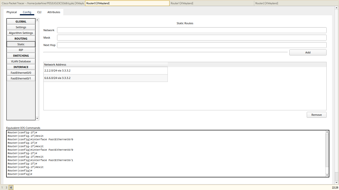
| ROUTER0 | FastEthernet0/0 | 1.1.1.1 |
| FastEthernet0/1 | 3.3.3.1 | |
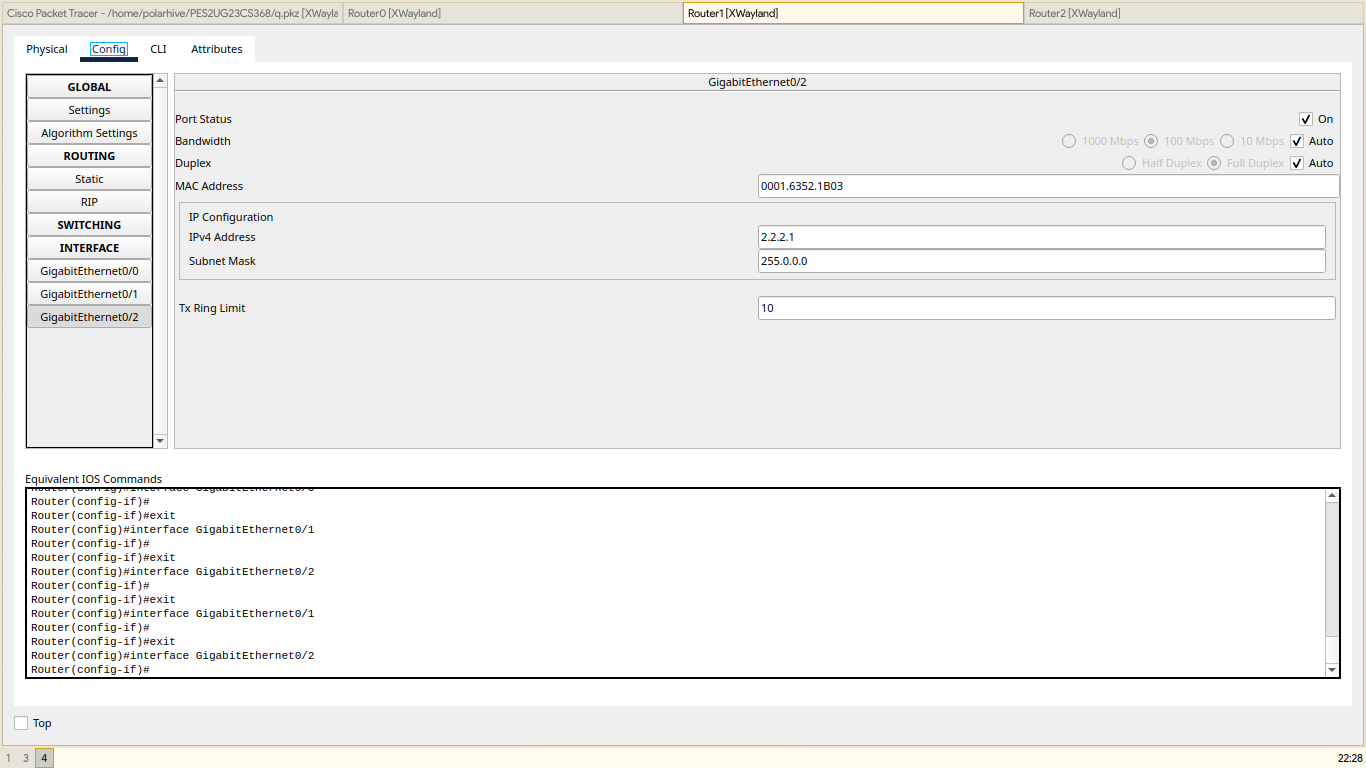
| ROUTER1 | GigabitEthernet0/0 | 3.3.3.2 |
| GigabitEthernet0/1 | 5.5.5.2 | |
| GigabitEthernet0/2 | 2.2.2.1 | |
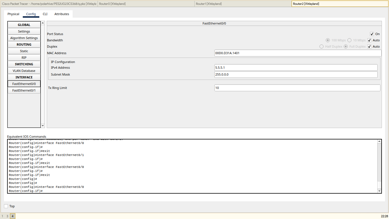
| ROUTER2 | FastEthernet0/0 | 5.5.5.1 |
| FastEthernet0/1 | 6.6.6.1 |
Router Table Entries
| Router # | Destination | Next Hop |
|---|---|---|
| ROUTER0 | 2.2.2.0 | 3.3.3.2 |
| 6.6.6.0 | 3.3.3.2 | |
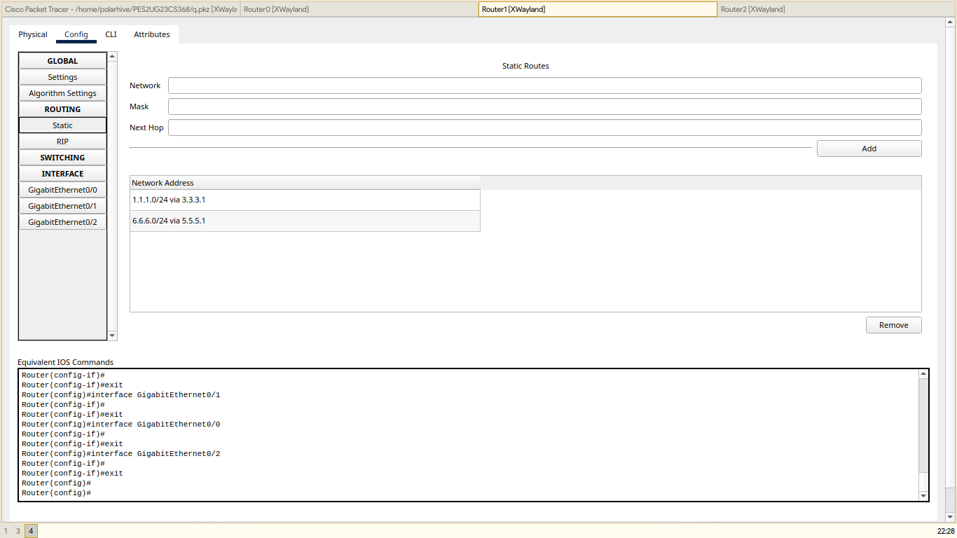
| ROUTER1 | 1.1.1.0 | 3.3.3.1 |
| 6.6.6.0 | 5.5.5.1 | |
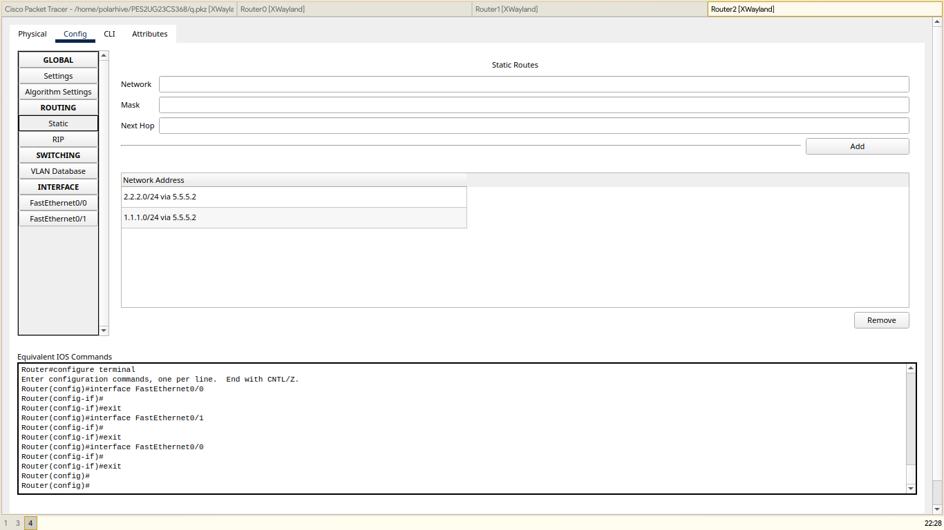
| ROUTER2 | 2.2.2.0 | 5.5.5.2 |
| 1.1.1.0 | 5.5.5.2 |